
The 9038 PCB replaces the 4747 and 4740 boards, in addition to the following information, Eagle or Tech Eagle version 3.40.2 or higher can be used to configure the boards if they need to be changed from the factory configuration.
A direct connect cable, part number 3859001, is required for connection between the 2903800 board and the PC. For more information, select the Help menu in Tech Eagle.
Options Switch
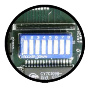
The options switch allows configuration of the RS-485 address, number of markers and alarm isolation.
| Switch | Function |
| 1 | Alarm Isolation OFF – Isolate (default) ON – report admin |
| 2-4 | RS-485 address |
| 5-7 | Number of markers |
Alarm Isolation
Setting switch #1 to ON allows a red alarm to be sent to other units over the master/slave sync. This feature is used to allow a slave beacon to send the rest of the system into white backup when a failure occurs in red night mode. The Master beacon will read the alarm and send all beacons into white backup. This is useful for stack systems that have all beacons at the same height and any failing beacon should cause the system to go to white backup. All units in the system must have the switch set to ON for this feature to be used. The default (OFF – Isolate) prevents slave units from causing the system to go to white back up if a red failure occurs on the slave.
Generally, a system should only go to white back up if the top (master beacon)
fails in red night mode.
RS-485 Communication

RS-485 is used to communicate with the FTM-5000 or FTW171-2 for monitoring of multiple beacon systems. The connections are available on J8 in the lower right corner. The pin assignments are shown below:
When all switches are OFF, the RS-485 is disabled. Once addressed, modem and RS-232 communication will be disabled and the RS-485 will become active. Switches #2-4 define the address as follows:
| 2 | 3 | 4 | Address |
| OFF | OFF | OFF | RS-485 disabled |
| ON | OFF | OFF | 1 |
| OFF | ON | OFF | 2 |
| ON | ON | OFF | 3 |
| OFF | OFF | ON | 4 |
Number of Markers
Switches #5-7 select the number of markers installed. Once set, the unit will alarm when the number of markers detected falls below this level (can change via Eagle or Tech Eagle).
| 5 | 6 | 7 | Markers |
| OFF | OFF | OFF | 0 |
| ON | OFF | OFF | 1 |
| OFF | ON | OFF | 2 |
| ON | ON | OFF | 3 |
| OFF | OFF | ON | 4 |
| ON | OFF | ON | 5 |
| OFF | ON | ON | 6 |
| ON | ON | ON | 7 |